Leave Your Message

What Is a Centrifugal Blower and How Does It Work?

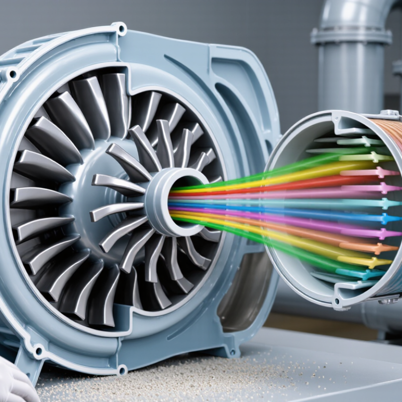
A Centrifugal Blower moves air by converting rotational energy into pressure and airflow. Its impeller draws air through the center, accelerates it outward, and guides it into a scroll-shaped housing. The housing slows the air and converts part of its velocity into useful static pressure. This process explains the blower’s familiar shape and its ability to overcome resistance in ducts, filters, heat exchangers, and industrial equipment.

The numbers matter.

The U.S. Department of Energy’s Fan System Assessment Tool identifies fans and blowers as important targets for industrial energy improvement. Its guidance connects operating efficiency with system resistance, control methods, maintenance, and motor selection. ASHRAE Handbook—HVAC Systems and Equipment also treats fan performance as a system issue, not merely an equipment rating. AMCA Publication 210 provides recognized laboratory procedures for measuring airflow, pressure, power, and efficiency. These references support a practical point: a high-efficiency blower can still waste energy when poorly selected or operated far from its design point.

In real use, a technician may hear belt vibration, feel unstable airflow, or find dust collecting near an inlet screen. Those details can reveal pressure loss or imbalance. Speed control often improves performance, but it cannot correct every design mistake. A small change in duct geometry may alter the operating point significantly. This is where simple explanations become incomplete. Understanding a Centrifugal Blower requires reading its performance curve, checking system resistance, and verifying measurements under actual conditions. Reliable decisions should combine manufacturer data, recognized test standards, field experience, and careful review.

What Is a Centrifugal Blower and How Does It Work?

What Is a Centrifugal Blower?

What Is a Centrifugal Blower?

A centrifugal blower is a mechanical device that moves air by changing its direction. Air enters near the center of a rotating impeller. The blades then push it outward through centrifugal force. Unlike an axial fan, it discharges air at a right angle to the inlet. Its basic parts include an impeller, housing, motor, inlet, and outlet. The housing often resembles a spiral shell.

Inside the housing, the spinning impeller increases air velocity. The curved casing then converts part of that velocity into pressure. This process helps the blower overcome resistance from ducts, filters, dampers, and heat exchangers. Pressure depends on speed, blade design, air density, and system resistance. The IEA’s Energy Efficiency 2023 report states that electric motor systems consume about 50% of global electricity. Blower efficiency therefore deserves careful attention, even in small installations.

Selection starts with airflow and required static pressure. Engineers should also check temperature, dust content, noise, and operating hours. A larger blower is not automatically better. Oversizing may create throttling losses and unstable operation. Undersizing can cause weak airflow and motor overload. The textbook picture is clean; field air is not. Dirty filters, leaking ducts, and inaccurate gauges can change performance quickly. AMCA Publication 210 provides standardized methods for measuring fan airflow and pressure, but real installations still need careful commissioning.

How Does a Centrifugal Blower Move Air?

What Is a Centrifugal Blower and How Does It Work?

A centrifugal blower moves air by changing its direction and increasing its pressure. Air enters near the center of a rotating impeller. The curved blades catch it and push it outward through centrifugal force. This movement resembles water leaving a spinning bucket. The air does not travel straight through the machine. It turns nearly 90 degrees before leaving the housing.

The blower’s casing collects this fast-moving air and guides it toward the outlet. Its wider shape helps convert some air velocity into useful pressure. In practical operation, a tight inlet seal and clean blades matter greatly. Dust buildup can disturb the airflow and increase vibration. I have seen a small layer of debris create noticeable noise during inspection. The fan still worked, but its performance was no longer stable.

Airflow depends on more than impeller speed. Duct length, bends, filters, and outlet resistance all affect the final volume. A blocked filter may make the blower sound powerful while delivering less air. That detail is easy to miss. Engineers usually check pressure and airflow together, rather than trusting sound alone. Measurements should match the system’s operating conditions. Even a carefully selected blower can underperform when the duct design is restrictive. The explanation is simple, but real installations are not always simple.

What Is a Centrifugal Blower and How Does It Work? - How Does a Centrifugal Blower Move Air?

Data Dimension Verified Information How It Affects Air Movement
Basic Definition A centrifugal blower is a mechanical device that uses a rotating impeller to move air or gas and discharge it in a direction approximately 90 degrees from the inlet flow. It changes the direction of airflow while generating a pressure increase that allows air to move through ducts, filters, heat exchangers, or process equipment.
Main Airflow Path Air typically enters through the impeller eye, moves radially outward through the impeller, and leaves through the blower housing outlet. The radial path distinguishes centrifugal blowers from axial fans, where air generally travels parallel to the rotating shaft.
Primary Energy Conversion The motor supplies rotational energy to the impeller. The impeller transfers velocity and kinetic energy to the air, while the housing converts part of that velocity into static pressure. This conversion enables the blower to overcome system resistance and maintain airflow against pressure losses.
Impeller The impeller is the rotating wheel fitted with blades or vanes. Its geometry, diameter, width, and blade angle influence the blower's performance. A larger or faster impeller generally increases air velocity and pressure, although the actual result depends on the complete system design.
Blower Housing The housing surrounds the impeller and commonly has a spiral or scroll shape that collects air and guides it toward the outlet. The expanding passage reduces air velocity and converts a portion of velocity pressure into static pressure.
Motor and Drive An electric motor commonly drives the impeller directly or through a belt-and-pulley arrangement. Some systems use variable-speed drives. Changing rotational speed changes the blower's airflow, pressure, power demand, and operating noise.
Pressure Capability Centrifugal blowers are generally selected when more pressure is required than a typical low-pressure axial fan can provide. The exact pressure range varies by impeller design, speed, size, and application. Higher pressure capability helps the blower move air through long ducts, dense filters, silencers, coils, and other restrictive components.
Airflow and Pressure Relationship Every blower has a performance curve showing the relationship between airflow and pressure. Increasing system resistance normally reduces the airflow delivered by the blower. The actual operating point occurs where the blower performance curve intersects the system resistance curve.
Static Pressure Static pressure is the pressure available to overcome resistance in the air system, including friction, fittings, filters, dampers, and equipment. A blower must generate sufficient static pressure for the required airflow; otherwise, the system may deliver inadequate ventilation or process air.
Velocity Pressure Velocity pressure is associated with the motion of air and increases as air velocity rises. The blower first adds velocity to the air, and the housing and downstream ductwork help recover part of that velocity as useful static pressure.
Blade Profiles Common impeller blade forms include forward-curved, backward-curved, and radial or straight-blade designs. Blade shape affects efficiency, sound level, power characteristics, resistance to material buildup, and suitability for clean or particulate-laden air.
Forward-Curved Blades Forward-curved impellers have blades that curve in the direction of rotation and can provide high airflow from a compact wheel. They are commonly used in applications requiring relatively high airflow at moderate pressure, but they can be more sensitive to overload and dirt accumulation.
Backward-Curved Blades Backward-curved impellers have blades that lean opposite to the direction of rotation and are often designed for efficient operation over a useful range. They are frequently selected where energy efficiency, stable performance, and a non-overloading power characteristic are important.
Radial or Straight Blades Radial-blade impellers use blades arranged approximately along radial lines and are mechanically robust. They are suitable for applications involving heavier dust, material handling, or air streams where durability and resistance to buildup are priorities.
Single- and Double-Inlet Designs A single-inlet blower draws air into one side of the impeller. A double-inlet design draws air into both sides. Double-inlet arrangements can provide greater airflow within a similar rotational speed range, subject to the blower's construction and available space.
Operating Speed Blower speed is normally expressed in revolutions per minute (rpm). For geometrically similar conditions, fan affinity laws indicate that airflow varies approximately with speed, pressure with speed squared, and power with speed cubed. Small speed increases can create a much larger increase in power demand, so speed changes must remain within the motor, impeller, and safety limits.
Efficiency Efficiency is the useful air power delivered divided by the input power required by the blower and drive system. Higher efficiency can reduce operating energy consumption, heat generation, and lifecycle cost.
System Resistance Resistance is created by duct friction, elbows, transitions, dampers, filters, grilles, coils, and other components. As resistance increases, the blower must operate at a higher pressure point, which usually reduces airflow and may increase energy use.
Common Applications Centrifugal blowers are used in HVAC systems, industrial ventilation, dust collection, combustion-air supply, drying equipment, cooling systems, and material-handling systems. Their ability to generate useful pressure makes them suitable for systems where air must travel through ductwork or process equipment.
Advantages Typical advantages include pressure generation, flexible installation orientation, compatibility with speed control, and availability of different impeller designs. These features allow one basic operating principle to serve clean-air, ventilation, cooling, and industrial process applications.
Limitations Performance is affected by incorrect sizing, excessive system resistance, dirty filters, impeller fouling, poor inlet conditions, and operation outside the rated speed range. Improper selection or maintenance can cause reduced airflow, vibration, noise, overheating, or excessive energy consumption.
Maintenance Priorities Routine maintenance commonly includes checking bearings, belts, guards, fasteners, vibration, impeller cleanliness, electrical connections, and system filters. Maintaining clean and balanced rotating components helps preserve airflow, pressure, efficiency, and operating safety.
Noise and Vibration Noise and vibration can result from aerodynamic turbulence, high air velocity, imbalance, misalignment, worn bearings, resonance, or loose components. Proper sizing, balanced impellers, flexible connections, vibration isolation, and suitable acoustic treatment can reduce unwanted sound and vibration.
Selection Criteria Key selection data include required airflow, total pressure, air temperature, density, gas composition, particulate loading, installation conditions, speed, efficiency, and allowable noise. Matching the blower to the complete system ensures that the required airflow is delivered reliably without overloading the motor or rotating assembly.

What Are the Main Parts of a Centrifugal Blower?

A centrifugal blower moves air by turning it outward with a rotating impeller. Air enters through the center, or eye, of the impeller. Curved blades then increase its velocity. The surrounding housing, called the volute, guides that fast air toward the discharge outlet. As the passage widens, part of the velocity changes into usable pressure.

The impeller is the working heart of the blower. Its blade shape, diameter, and balance strongly affect airflow, noise, and power demand. A shaft connects the impeller to an electric motor or another drive system. Bearings support the shaft and must handle continuous rotation without excessive heat. Even a small alignment error can create vibration. That detail is easy to underestimate.

The inlet controls how smoothly air reaches the impeller. Screens, filters, or flexible connectors may protect internal parts, but dirty filters restrict performance. The discharge outlet directs air into ductwork or process equipment. Seals limit leakage around the shaft, while a sturdy frame keeps the assembly stable. Temperature and vibration sensors can reveal early problems. In practice, technicians often inspect the inlet first, although bearing wear may be the real cause. Maintenance records should include operating speed, pressure, temperature, and unusual sound. A blower can still run while gradually losing efficiency.

How Does the Airflow Process Work Step by Step?

A centrifugal blower moves air by converting rotating mechanical energy into airflow and pressure. The process begins at the inlet, where low pressure draws surrounding air into the blower housing. Air enters near the center of a spinning impeller. The blades capture it and push it outward through centrifugal force. As the air leaves the impeller, its velocity increases sharply. This fast-moving air then enters the volute or diffuser section around the impeller.

The sequence sounds simple. The housing gradually expands, giving the air more space to move. Its velocity decreases, while part of that energy changes into static pressure. The pressurized air travels toward the discharge outlet and enters a duct, filter, or ventilation system. System resistance then determines how much air actually moves. A blocked filter, narrow duct, or sharp bend can reduce airflow noticeably.

In practical inspections, technicians often check pressure readings, vibration, temperature, and unusual noise together. A humming sound may indicate imbalance, while rattling can suggest loose hardware or damaged blades. Airflow is rarely perfect. Small leaks around joints can waste pressure before the air reaches its destination.

Engineers also compare measured performance with the blower curve, because motor speed alone cannot confirm proper operation. This step-by-step check is easy to overlook, yet it reveals problems that visual inspection may miss.

What Factors Affect Centrifugal Blower Performance?

What Is a Centrifugal Blower and How Does It Work?

A centrifugal blower draws air into a rotating impeller and turns it outward through centrifugal force. The casing then converts part of that velocity into pressure. Performance depends on more than motor size. Flow rate, static pressure, air density, temperature, and system resistance all interact. A blower moving hot air, for example, handles less mass than it moves at room temperature.

Speed is especially influential. Under the fan affinity laws, published by the U.S. Department of Energy in Improving Fan System Performance, flow changes roughly with speed, pressure with speed squared, and power with speed cubed. A 10% speed increase may raise power demand by about 33%. That is not a small adjustment. The same source reports that fan systems can represent 15–20% of industrial electricity use, making control decisions financially important.

Inlet restrictions, dirty filters, sharp elbows, and poor discharge transitions can reduce useful airflow. Leakage also wastes pressure before air reaches the process. AMCA test guidance emphasizes standardized measurements for flow, pressure, power, and efficiency, yet field conditions rarely look perfect. A clean laboratory curve can mislead. Operators should compare measured readings with the design point, not rely only on catalog values. Variable-speed control often improves efficiency, but oversizing remains common and deserves honest review. A quieter blower is not automatically a better blower.