Leave Your Message

What Is a Side Channel Air Blower and How Does It Work?

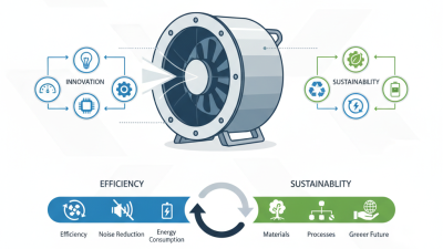
A Side Channel Air Blower is a compact machine designed to move air continuously at moderate pressure or vacuum levels. It appears in wastewater aeration, pneumatic conveying, packaging equipment, printing systems, and industrial drying. Unlike a basic fan, it can create stronger air pressure. Unlike many compressors, it normally operates without oil in the airflow.

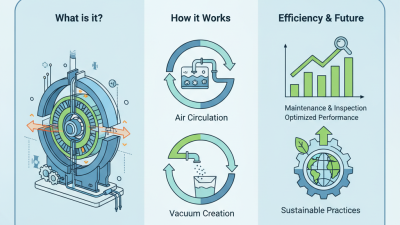
Its working principle is straightforward. An electric motor spins a specially shaped impeller inside a precisely engineered housing. Air enters through the inlet and follows a spiral path around the side channel. Each impeller rotation adds energy to the moving air. This repeated acceleration increases pressure or produces vacuum, depending on the connection and system design. The outlet then sends air through pipes, filters, diffusers, or suction lines.

Small details matter. A blocked filter can reduce performance and raise operating temperature. An undersized pipe may create unnecessary resistance. Noise, vibration, and motor current can reveal problems before failure occurs. In real installations, correct sizing depends on airflow, pressure, duty cycle, altitude, and air temperature—not the blower label alone.

It is not magic.

A side channel blower may be selected incorrectly when users compare only maximum airflow. That approach can disappoint. Actual performance changes under system resistance, and published curves must be read carefully. Reliable guidance combines manufacturer data, measured operating conditions, and practical maintenance experience. This article explains the internal airflow path, common configurations, advantages, limitations, and key selection considerations, while recognizing that every application has different demands.
What Is a Side Channel Air Blower and How Does It Work?

Definition and Main Components of a Side Channel Air Blower

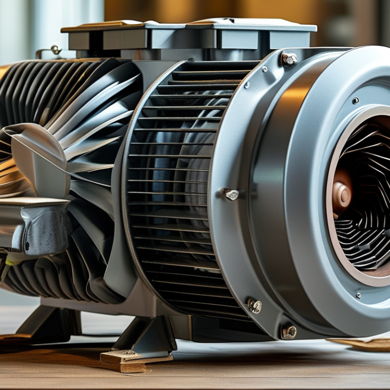
A side channel air blower is a centrifugal machine that moves air through repeated pressure-building stages. Unlike a standard fan, it can create stronger vacuum or pressure for its size. Air enters through an inlet port and reaches a fast-spinning impeller. Curved blades push the air into a ring-shaped side channel. The air circulates, gains energy, and returns to the impeller repeatedly. This creates steady airflow without direct contact between rotating and stationary parts.

The main components include an electric motor, impeller, housing, inlet, outlet, shaft, bearings, and protective guards. The motor turns the shaft, while the shaft drives the impeller. Precision bearings support rotation and help reduce vibration. The housing guides airflow through the side channel. Seals limit leakage, although no seal remains perfect forever. In practical maintenance, dust, blocked filters, and excessive back pressure often cause more trouble than mechanical failure. Heat may build quickly when airflow is restricted. That detail is easy to overlook.

Tips: Check the inlet filter regularly and keep ventilation openings clear. Listen for unusual noise or pulsing airflow. Compare operating pressure with the equipment’s rated range. A simple pressure gauge can reveal problems before they become expensive. Lubrication requirements vary by design, so avoid adding oil without checking the service instructions. Small checks matter.

How the Impeller Generates Airflow at 2,850–3,450 rpm

A side channel air blower moves air without a conventional compressor piston. Its impeller spins inside a close-fitting housing. At 2,850–3,450 rpm, curved blades repeatedly capture and redirect air. This rapid motion creates a low-pressure inlet and a steady discharge flow. It is continuous.

Air enters near the impeller eye, then travels through the side channel. Each blade pass adds energy, while the channel guides air around the casing. The air follows a spiral path, not a straight push. Small clearances help maintain pressure, but they also make cleanliness important. During field checks, I look for blocked filters, hot bearings, and unusual vibration. These details often explain weak airflow better than motor speed alone.

Higher speed can increase airflow and pressure, but it also raises noise and heat. A blower running at 3,450 rpm may feel powerful, yet poor duct design can waste that energy. Measure inlet vacuum, discharge pressure, temperature, and current under real load. Sound can mislead. One practical limitation remains: the impeller needs stable operating conditions. Pulsing demand, dirty air, or a restricted outlet can reduce efficiency. Diagrams make this principle look perfectly simple. Actual systems are less forgiving.

Pressure, Vacuum, and Flow Ratings: Up to 600 mbar and 2,000 m³/h

A side channel air blower moves air through a rotating impeller and a circular side channel. Air enters near the hub, gains velocity, and circulates repeatedly before discharge. This creates pressure for conveying air or vacuum for lifting and extraction. There is no oil in the air path. That can simplify maintenance.

The headline rating needs careful reading. A unit marked up to 600 mbar delivers about 60 kPa of gauge pressure under restricted flow. A listed capacity of 2,000 m³/h equals roughly 0.56 m³/s at an open outlet. These figures are usually peak values, not simultaneous operating points. As pressure rises, available airflow falls. The performance curve matters more than either headline number.

For example, a process needing 350 mbar may receive far less than 2,000 m³/h. Pipe length, elbows, filters, silencers, and dirty intake screens increase system resistance. The U.S. Department of Energy’s Improving Compressed Air System Performance sourcebook reports that poorly maintained systems can lose 20–30% of capacity through leakage. That figure concerns compressed-air systems, but it highlights a similar lesson: small losses become expensive at scale. ISO 5801 and AMCA 210 describe standardized airflow and pressure testing methods, yet field conditions still differ. I would verify the test medium, temperature, inlet restriction, and whether pressure is gauge or absolute. Many specifications remain unclear there.

Motor Power, Noise Levels, and Typical Efficiency Ranges

A side channel air blower is a compact machine for moving air at moderate pressure. It uses a fast-spinning impeller inside a shaped channel. Air enters near the center, gains velocity, and circulates through the channel several times. This repeated movement increases pressure without direct contact between the impeller and housing. That matters.

Motor power usually ranges from about 0.25 to 15 kW in common industrial equipment. Smaller motors suit light suction, air tables, and small conveying systems. Larger motors handle deeper vacuum or higher pressure demands. A higher rating does not always mean better performance. The blower must match the system’s airflow resistance and operating point.

Noise commonly falls between 55 and 80 dB(A), measured at a specified distance. High speed, restricted filters, and vibration can raise the reading. In practice, a simple enclosure may reduce noise, but it can also trap heat. This detail is often overlooked. Operators should check motor temperature during continuous use.

Typical wire-to-air efficiency sits around 30% to 60%, depending on pressure, airflow, motor size, and measurement method. Well-matched systems perform near the upper part of that range. Poorly selected units may consume substantial power while moving surprisingly little air. I would not treat published efficiency as a fixed promise; duct losses and dirty filters change real results. A pressure gauge, airflow measurement, and power meter provide more reliable evidence than sound alone.

Industrial Applications, Sizing Criteria, and Maintenance Requirements

A side channel air blower uses a high-speed impeller to move air through a circular side channel. Air gains velocity, returns to the impeller, and receives repeated energy increases. This creates moderate pressure or vacuum without direct contact between moving parts and the housing. Many designs keep oil away from the air stream. Common applications include wastewater aeration, pneumatic conveying, vacuum lifting, packaging, and printing machinery.

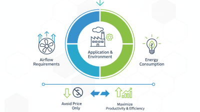
Sizing requires more than matching a motor’s horsepower. Specify the required airflow, pressure or vacuum, duty cycle, inlet temperature, altitude, and filtration level. A neat calculation can still be wrong. The U.S. Department of Energy’s Improving Compressed Air System Performance sourcebook reports that leaks can waste 20–30% of compressor output. Its guidance also links lower operating pressure with energy savings, often near 1% for each 2 psi reduction, when demand remains satisfied. These figures concern compressed-air systems, but they highlight a useful blower principle: avoid excessive pressure margins. Check performance curves at the actual operating point, not only the rated maximum.

Tips: Record baseline current, vibration, airflow, and casing temperature. Inspect inlet filters frequently. A blocked filter can raise vacuum and motor load. Listen for bearing noise. Check relief valves and pipe joints. Clean deposits from the impeller and channel. Follow the maintenance interval in the service manual, but adjust it for dust, moisture, and continuous operation. Field technicians sometimes replace filters too late; this small oversight can distort readings and shorten bearing life. Use CAGI-style performance data where available, and verify measurements onsite before approving a larger unit.