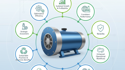
Selecting a High Pressure Regenerative Blower manufacturer in 2026 requires more than comparing catalog pressure ratings. Buyers must examine airflow at operating pressure, noise, power draw, materials, and service access. A blower may look impressive on paper, yet perform poorly when filters clog or duct losses rise. Small details matter.
The U.S. Department of Energy and Compressed Air Challenge’s Improving Compressed Air System Performance sourcebook reports that leaks can waste 20–30% of compressor output in poorly maintained systems. That figure describes compressed-air systems broadly, not regenerative blowers alone. Still, it highlights why efficiency claims need context and why test conditions should be checked. The Compressed Air and Gas Institute’s performance-testing guidance also makes comparable, documented measurements important when evaluating equipment.
Compressed-air specialist Ron Marshall’s published guidance emphasizes measuring performance at the point of use, where pressure losses affect real operation. Put simply: “Check the delivered pressure, not just the nameplate.” This is a concise paraphrase, not a verbatim quotation. It points to a practical question for every manufacturer: can the supplier support its ratings with clear test data and application guidance?
This 2026 overview examines leading manufacturers through that lens. It considers product range, documented performance, customization, and after-sales support. Rankings can never capture every plant condition. A careful shortlist—and a little healthy skepticism—still helps.
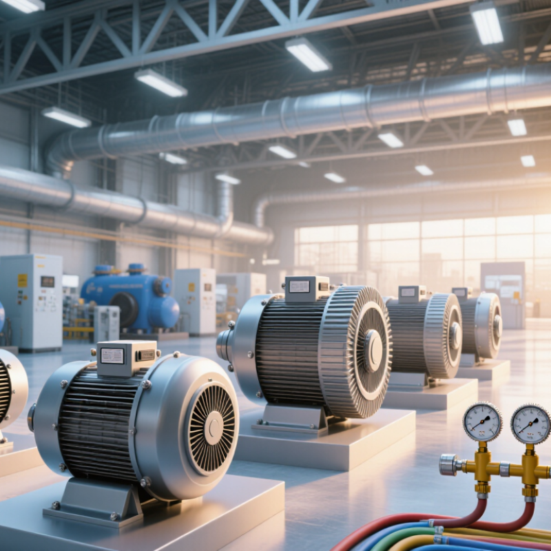
A regenerative blower moves air through a narrow side channel. Its impeller blades repeatedly accelerate the air, returning it to the channel before discharge. This recirculation builds pressure gradually rather than in one compression event. The result is steady, oil-free airflow for applications such as aeration, vacuum conveying, and drying.
Pressure and airflow are linked. As backpressure rises, delivered airflow generally falls, so a blower’s maximum pressure and maximum flow should not be treated as simultaneous operating points. Check the performance curve at the actual system resistance, including filters, pipe bends, and outlet restrictions. That distinction matters. A small duct change can shift the operating point more than expected.
System losses also deserve attention. The U.S. Department of Energy’s Improving Compressed Air System Performance sourcebook reports that leaks can waste 20–30% of compressed-air output in some plants. That figure is not specific to regenerative blowers, but it highlights why leak checks matter in air networks. Small leaks add up. In practice, measure pressure and airflow at the point of use; readings at the blower outlet alone may give an incomplete picture.
A slightly awkward lesson: the “right” blower can still perform poorly when the installation is wrong.
In 2026, leading regenerative blower manufacturers compete on more than maximum pressure. Buyers should compare airflow at the required operating point, power draw, sound levels, and the materials used in the air path. A blower’s performance can change as system resistance rises, so a headline rating alone may not reflect conditions on the factory floor. Ask for a performance curve and confirm the test conditions.
Design priorities differ across established European and international suppliers. Some configurations favor compact installation; others emphasize service access, quieter operation, or options for demanding duty cycles. Check whether the package includes suitable inlet filtration, pressure relief, and clear temperature limits. These details matter in packaging lines, pneumatic conveying, and equipment cooling. Small choices add up.
A careful selection starts with the process, not the catalog. Record the needed flow, pressure, ambient temperature, and daily operating hours, then compare models on the same basis. Requesting references for similar applications can help, though one installation is not proof of universal performance. I would also leave room for uncertainty: duct losses, leaks, and dusty filters can undermine a neat calculation. Plan for inspection and measure the installed system after startup.
This manufacturer-neutral overview summarizes established regenerative-blower principles and selection factors. Actual performance depends on the specific model, operating point, gas, and installation; consult published performance curves for equipment comparisons.
| Evaluation Dimension | Factual Overview | What to Check When Selecting |
|---|---|---|
| Operating principle | An impeller repeatedly accelerates gas around a side channel, transferring energy to generate pressure or vacuum. | Confirm that regenerative technology suits the required flow and differential pressure; it is not interchangeable with every positive-displacement or centrifugal design. |
| Pressure and vacuum | A regenerative blower can be configured for pressure service, vacuum service, or both. There is no single universal pressure limit for the technology. | Compare the required differential pressure with the model’s published curve at the intended flow, gas, and inlet conditions. |
| Flow and operating point | Delivered flow changes as differential pressure changes. The fan curve, system resistance, and gas density determine the actual duty point. | Check the full pressure-flow curve rather than relying on a maximum-flow or maximum-pressure figure alone. |
| Gas and temperature | Standard configurations are commonly intended for air. Other gases, elevated temperatures, or corrosive or combustible conditions may require specially suitable materials or designs. | Verify gas compatibility, temperature limits, sealing, and any applicable safety or hazardous-area requirements with the equipment supplier. |
| Compression chamber | Many regenerative blowers operate without oil lubrication in the gas-handling chamber; this does not by itself guarantee contaminant-free outlet air. | Review the construction and required outlet-air quality. Add filtration or treatment if the process requires it. |
| Thermal management | Gas compression and motor losses produce heat. Permissible temperature rise depends on the blower design, duty, ambient conditions, and airflow. | Check continuous-duty limits, cooling and ventilation clearances, ambient temperature, and any required temperature protection. |
| Noise and vibration | Sound and vibration levels vary with model, speed, operating point, mounting, and connected pipework. | Request rated sound data under stated test conditions and consider resilient mounting, silencers, and suitable pipe supports where needed. |
| Installation safeguards | Blocked lines, excessive restriction, or operation outside the rated envelope can cause overheating or equipment damage. | Follow the installation manual; assess inlet filtration, pressure or vacuum relief, airflow restrictions, and electrical protection for the application. |
| Maintenance | Service needs depend on the model and operating environment. Inlet filters, clearances, bearings, electrical connections, and cooling passages may require inspection. | Use the manufacturer’s maintenance schedule and check filter condition and system restrictions at intervals appropriate to the site. |
| Typical applications | Common uses include aeration, pneumatic conveying, drying, vacuum lifting, and air-knife or air-cushion systems, subject to suitable duty and gas conditions. | Match the blower to the process duty, required air quality, operating cycle, and system losses before final selection. |
When comparing high pressure regenerative blower manufacturers, rated flow should be read alongside differential pressure, not in isolation. A listed flow of 500 m³/h may apply near free discharge, where resistance is low. Ask for the performance curve and locate the flow at your actual operating pressure. That point matters.
Differential pressure, shown in kPa, indicates the pressure rise the blower can sustain across the system. Compare units at the same inlet conditions and duty point. A long hose, narrow pipe, or clogged filter can reduce delivered flow. Small details change the result. A table alone will not show this.
Motor power in kW helps indicate the drive size, but it does not tell you the full operating cost. Check whether the figure is rated motor output or electrical input, and confirm the required supply and continuous-duty rating. Match the motor to the pressure-flow point, with a sensible operating margin. I would also verify noise, cooling, and service access; these are easy to overlook. Manufacturer data can differ in test conditions, so request comparable figures before choosing.
For 2026 manufacturer comparisons, request separate 50 Hz and 60 Hz performance curves tested using ISO 5801:2017 methods. The standard sets out fan performance testing with defined test arrangements, helping buyers compare airflow, pressure, and input power on a consistent basis. Check whether each curve reports static or total pressure. They are not interchangeable. Small details matter.
At the same impeller diameter and similar air density, the fan affinity laws offer a useful first estimate: changing speed from 50 Hz to 60 Hz may raise flow by about 20%, pressure by 44%, and shaft power by 73%. Treat these as estimates, not guarantees; motor slip, controls, and regenerative blower behavior can shift actual results. The International Energy Agency’s 2011 report, Energy-Efficiency Policy Opportunities for Electric Motor-Driven Systems, estimates motor-driven systems use about 45% of global electricity. That makes verified power data relevant, not decorative.
When reviewing a curve, match the test setup, inlet temperature, air density, and operating point to your installation. Look closely at the duty point, not just the highest pressure figure. Ask for measured efficiency and power at both frequencies, and confirm the test method and uncertainty are stated. A curve without conditions is hard to trust.
Illustrative pressure–flow curves scaled using fan affinity laws; values are not measured data for a specific blower.
The example applies the approximate affinity-law relationships for the same blower: airflow scales with rotational speed, while pressure scales with the square of speed. ISO 5801 provides standardized methods for determining fan performance; use measurements from an ISO 5801 test to assess a specific product.
Industrial applications should guide blower selection. Regenerative blowers commonly support wastewater aeration, pneumatic conveying, and vacuum handling. Each duty has a different airflow pattern and pressure requirement. A blower sized for steady aeration may struggle when a process demands frequent starts or changing flow. Check the operating point against the full duty cycle, not just the equipment nameplate.
Maintenance needs are often modest, but they are not zero. Keep inlet filters clear, inspect connections for leaks, and monitor bearing noise and operating temperature. Dust buildup can restrict airflow and raise heat. Air demand fluctuates. That matters when comparing units for a process with variable loads. Confirm service access and replacement-part availability before installation; a compact layout can make routine checks surprisingly awkward.
Lifecycle cost includes purchase price, electricity, downtime, and scheduled service. Compare energy use at the expected operating point, since a low initial price may not mean lower long-term cost. Estimate annual running hours and electricity rates, then test more than one demand scenario. These calculations are useful, but they can still miss real operating changes. Revisit assumptions after commissioning and record actual power use, pressure, and maintenance intervals.