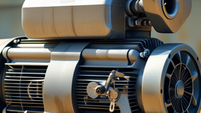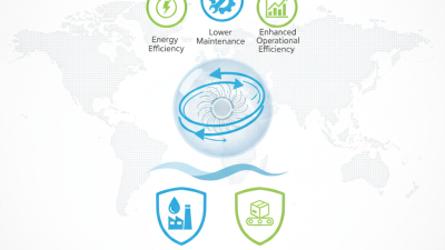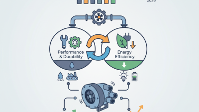
A Regenerative Blower moves air without an impeller touching the casing. Its compact housing can produce steady airflow for applications such as aeration, vacuum handling, and pneumatic conveying. But what happens inside that housing? Air enters near the inlet, then a rotating impeller repeatedly recirculates it through narrow side channels. Each pass adds energy before the air leaves through the outlet. The result is a simple operating principle, though actual performance depends on pressure, flow, temperature, and installation conditions.
The U.S. Department of Energy’s Improving Fan System Performance: A Sourcebook for Industry estimates that fans account for about 7% of electricity use in U.S. manufacturing. That figure covers industrial fans broadly, not regenerative blowers alone. It still highlights why selecting equipment by duty point matters. A blower that runs against excessive resistance can waste energy, create heat, and deliver less useful airflow. Small details count. Check the filter, pipe diameter, noise, and discharge temperature.
This guide explains the blower’s main components, airflow path, and practical limits. It also distinguishes pressure capability from flow capacity, two specifications that are easy to confuse. A named expert quotation has not been included because no verifiable, topic-specific source was provided; inventing one would weaken reliability. That limitation matters. Understanding the mechanism is only the start: matching the unit to the process is where sound engineering shows.
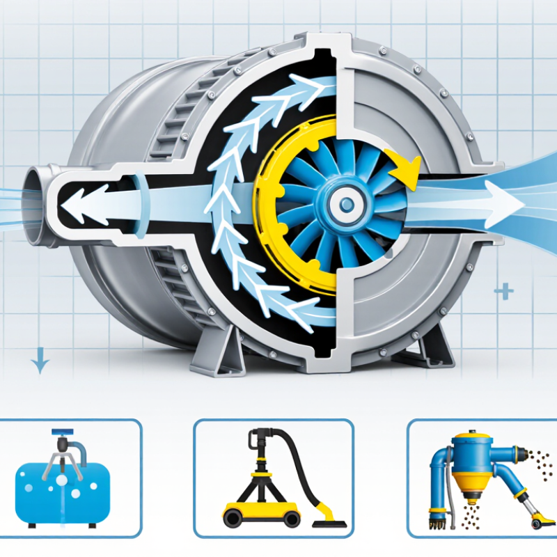
A regenerative blower is a dynamic air mover that produces pressure or vacuum through repeated energy transfer between a rotating impeller and the air. It is also called a side-channel blower. Its impeller has many small blades, and it spins inside a close-fitting housing. Air enters near the inlet, circulates through the side channel, and gains energy with each pass before leaving through the outlet.
The motion is continuous. There are no contacting vanes or internal compression chambers, so the design has few wearing parts. That does not mean maintenance-free. Dust, heat, blocked filters, or a restricted outlet can reduce performance or raise operating temperature. In practice, checking airflow and pressure at the actual installation matters more than relying on a catalog’s maximum figures.
A regenerative blower suits steady, moderate-pressure applications, such as aeration, vacuum conveying, and drying. Its flow usually falls as backpressure rises, so it is not a fixed-flow device. The U.S. Department of Energy’s Improving Compressed Air System Performance sourcebook reports that leaks can waste 20–30% of compressed air in many plants. That figure applies to plant air systems, not specifically to blower efficiency, but it shows why selecting the right pressure and checking the whole air path matters. A small leak still counts.
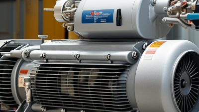
A regenerative blower centers on an impeller, a close-fitting housing, and a motor. The impeller carries many small radial blades. As it spins, air enters through the inlet and is caught between the blades. The housing forms a narrow side channel around the impeller. Air moves outward, returns toward the blades, and receives another increment of energy with each pass. This repeated circulation creates pressure or vacuum, depending on the system connection. Small clearances matter.
The motor and shaft provide rotation, while bearings support the shaft and help keep the impeller aligned. Inlet and discharge ports guide airflow; screens or filters may protect the channel from dust and fibers. A cover and seals limit leakage, though they do not make every unit airtight. Heat also needs attention. Compression and friction can warm the air and housing, so operating limits and ventilation should match the duty cycle. Noise often comes from airflow and vibration, not just the motor. Check the full installation, not only the blower: a kinked hose, blocked filter, or undersized line can reduce performance. Exact layouts vary, and a cutaway drawing may be needed to identify each part confidently.
Illustrative airflow vs. pressure curve
A motor spins an impeller inside a close-clearance housing. Air recirculates through the impeller’s blades, gaining energy with each pass before leaving through the outlet. The chart illustrates the typical trend: airflow decreases as pressure differential rises. Values are illustrative, not a specification for a particular blower.
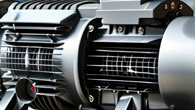
Key components: the motor drives the impeller; the impeller adds energy to the air; the housing guides airflow; and the inlet and outlet direct air into and out of the blower.
Air enters through an inlet and reaches a fast-spinning impeller. Its curved blades push the air outward, toward a narrow channel around the impeller. The channel guides the air back toward the blades, where it receives another push. This repeated circulation is the defining action of a regenerative blower. Think of a small stream looping past a row of paddles. Each pass adds energy.
The air does not simply cross the housing once. It travels through the side channel in a spiral-like path, gaining pressure as the impeller transfers energy to it repeatedly. Near the outlet, a divider separates the returning flow from the discharge flow. The energized air then leaves through the outlet connection. The exact path depends on the blower’s internal geometry, so a diagram may simplify what happens inside.
This process can provide steady airflow in a compact unit, but it also warms the air. That matters. A blocked inlet, dirty filter, or restricted outlet can change operating conditions and raise temperature. In practical installations, check the specified pressure and flow range, and allow enough ventilation around the housing. The mechanism sounds simple; real airflow is less tidy. Ambient temperature and system resistance can affect performance, so measurements under actual operating conditions are more useful than assumptions.
A regenerative blower moves air through a rotating impeller and a circular side channel. Air repeatedly gains energy as it travels around the channel, creating pressure or airflow for the connected system. Actual output depends on the operating conditions, not just the blower’s rated capacity. A narrow inlet, clogged filter, or undersized pipe can restrict flow before air reaches the impeller. Keep the inlet clear. Even a modest blockage can change the sound and temperature of the unit.
Discharge backpressure also matters. Long hoses, sharp bends, and restrictive valves make the blower work harder and can reduce delivered airflow. Motor speed and supply voltage affect performance too, while hot intake air is less dense and may alter the amount of air moved. Installation deserves attention: a cramped, poorly ventilated space can trap heat around the housing. It is tempting to blame the motor, though that is not always fair. Check the filter, pipework, and pressure readings before drawing conclusions. Measure under real operating conditions. A rated figure alone rarely tells the whole story.
Regenerative blowers are often used when a process needs steady, moderate airflow or vacuum rather than extreme pressure. In wastewater treatment, they supply air to diffuser grids at the bottom of aeration tanks. Aquaculture systems use them to keep oxygen moving through water. Packaging lines may use vacuum to hold lightweight sheets in place, while some conveying systems move small, dry materials through pipes. The blower’s impeller repeatedly moves air around a side channel, adding energy with each pass. There are no sliding vanes inside the air path. Small details matter.
Check the required airflow and pressure against the blower’s performance curve, not just its maximum rating. A long, narrow pipe, clogged filter, or sharp bend can change operating conditions and raise temperatures. Keep inlet air clean and dry; dust and moisture can shorten service life. Leave clearance around the unit so its motor can shed heat, and account for noise in occupied work areas. A relief valve can help protect equipment if the outlet becomes blocked. One point deserves a second look: a regenerative blower is not a universal substitute for a compressor or central vacuum system. Its suitability depends on the actual duty cycle, piping, and process needs, which are sometimes harder to estimate than the equipment itself.
| Topic or Application | How It Works | Typical Operating Mode | Common Use | Key Operating Considerations |
|---|---|---|---|---|
| Regenerative blower principle | An impeller with vanes transfers energy to gas. The gas circulates through a side channel and receives repeated energy input as it travels from inlet to outlet. | Continuous airflow with a pressure rise or vacuum, depending on how the system is connected. | Applications needing steady, oil-free air movement at a relatively low-to-moderate pressure differential. | Performance depends on the selected blower and the system resistance. It is a dynamic air mover, not a substitute for a high-pressure compressor. |
| Wastewater aeration | Air is supplied through diffusers or other aeration equipment to transfer oxygen into water. | Pressure operation; the blower must overcome water depth, diffuser losses, and pipe resistance. | Small treatment systems, tanks, and process-water aeration. | Check required airflow and total system pressure. Keep inlet filters clean and ensure the motor and blower are suitable for continuous duty. |
| Pneumatic conveying | Moving air carries lightweight or compatible bulk material through a conveying line. | Usually pressure conveying; some systems use vacuum conveying. | Transfer of powders or granules over short distances where the required pressure differential is within the blower’s rating. | Confirm material compatibility, conveying-line losses, and the possibility of dust entering the blower. Use appropriate filtration and safeguards. |
| Vacuum lifting and hold-down | The blower removes air from a circuit to create a pressure difference that holds or lifts a workpiece. | Vacuum operation; achievable vacuum depends on airflow, leakage, and system design. | Porous-material handling, packaging equipment, and vacuum hold-down tables. | Account for leakage and the workpiece’s porosity. A regenerative blower generally provides airflow under leakage better than a deep-vacuum pump. |
| Drying and cooling | A directed stream of air removes moisture or carries heat away from a surface or process. | Pressure operation, commonly with an air knife, nozzle, or ducted outlet. | Surface drying, cooling of components, and air supply for equipment. | Allow for outlet restrictions and backpressure. Avoid operating with blocked inlets or outlets, which can cause excessive heat. |
| Air supply for process equipment | Air is delivered to a process that needs a continuous, comparatively clean airflow. | Pressure or vacuum, as specified by the process and piping arrangement. | Air cushions, agitation, and other low-to-moderate pressure process duties. | Verify gas compatibility, required flow, pressure differential, ambient temperature, and duty cycle before selecting equipment. |
| Installation and maintenance | The impeller rotates at high speed; normal operation relies on clear airflow paths and suitable operating conditions. | Install with adequate ventilation and access for inspection. | Applies to all blower installations. | Use correctly sized piping and filters; inspect for dust buildup, unusual vibration, noise, or overheating. Follow the equipment’s rated limits and maintenance instructions. |
Selection note: Pressure, vacuum, airflow, temperature limits, and continuous-duty capability vary by design. Confirm the required operating point against the specific equipment curve and the complete system pressure-loss calculation.